Two-Stage Gear Reducer Design
Technical Datasheet
MECH-002Project Overview
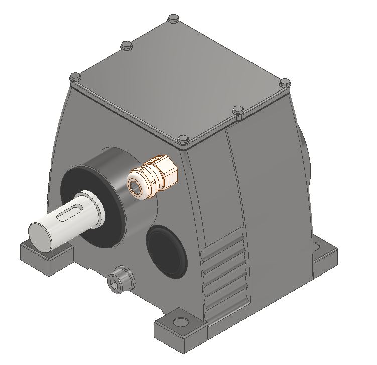
A complete analytical and graphical design of a two-stage cylindrical gear reducer with a single-piece housing. The project involved calculating multiple gear ratio variants, selecting the optimal transmission configuration, choosing a suitable electric motor based on output torque requirements, and generating manufacturing documentation.
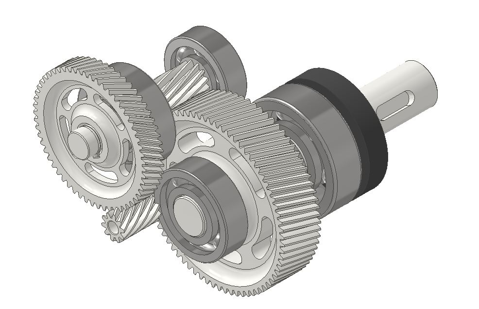
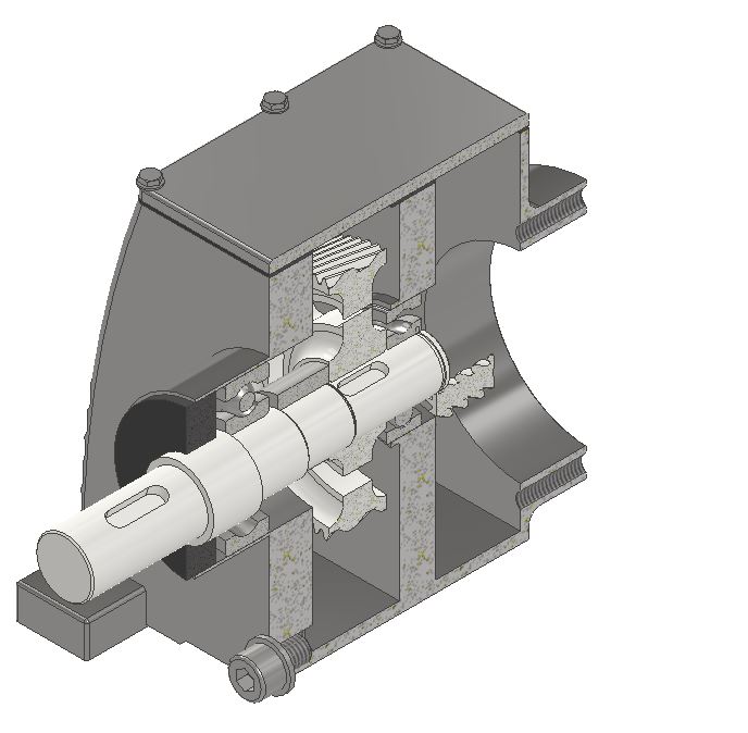
The final design—consisting of shafts, gears, bearings, and reducer housing—was fully modeled as a 3D assembly in Autodesk Inventor, following technical standards for gear design and machine elements.
The final design—consisting of shafts, gears, bearings, and reducer housing—was fully modeled as a 3D assembly in Autodesk Inventor, following technical standards for gear design and machine elements.
Key Engineering Tasks
- Gear Geometry Calculation: Preliminary and detailed calculation of helical gear geometry and strength.
- Ratio Optimization: Multi-variant analysis to select the optimal transmission ratio based on torque and motor compatibility.
- Component Selection: Electric motor selection (SEW/Sever catalogs) and bearing life calculation.
- System Layout: Detailed arrangement of shafts, gears, bearings, and housing geometry.
- Manufacturing Documentation: Creation of workshop drawings for input shaft, output gear, and full assembly.
- 3D Modeling: Complete 3D assembly in Autodesk Inventor based on analytical results.
Tools & Technologies
Autodesk Inventor
Manual Gear Calculations (ISO)
Microsoft Excel
SEW & Sever Catalogs
Machine Elements Standards
3D Assembly Model
Project Gallery