V6 Internal Combustion Engine (Conceptual CAD Design & Full Assembly)
Technical Datasheet
MECH-003Project Overview
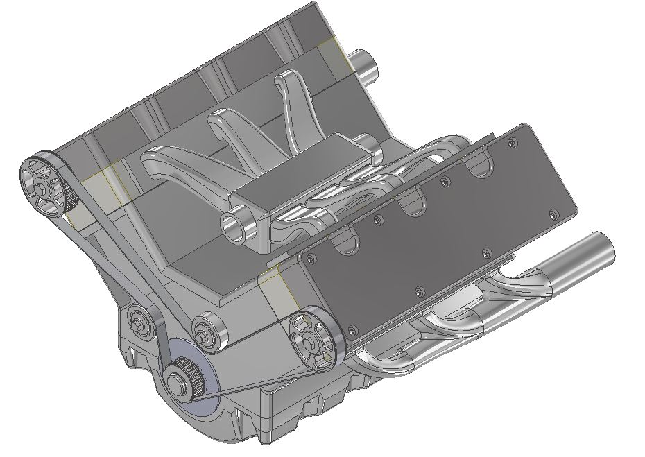
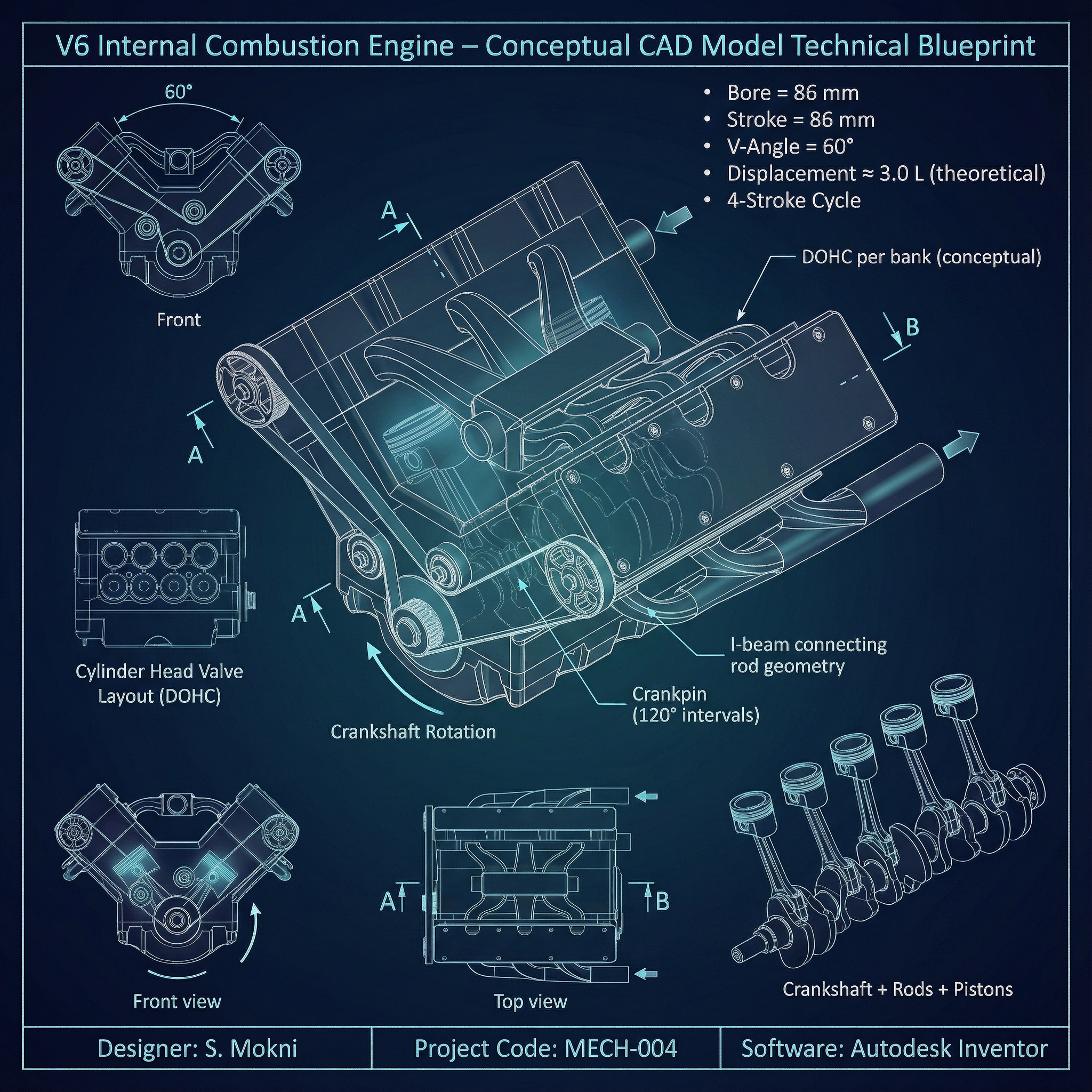
This project consists of the complete CAD design of a V6 internal combustion engine created from scratch in Autodesk Inventor. The work combines mechanical theory, engineering references, textbook parameters, and extensive CAD practice to better understand how real engines are structured and assembled.
The engine model follows realistic proportions and relationships, although it is not based on a specific manufacturer model nor intended for physical simulation. Its purpose is to represent a technically coherent V6 layout and serve as a practice platform for advanced CAD modeling and assembly logic.
The engine model follows realistic proportions and relationships, although it is not based on a specific manufacturer model nor intended for physical simulation. Its purpose is to represent a technically coherent V6 layout and serve as a practice platform for advanced CAD modeling and assembly logic.
Key Engineering Tasks
- Part Modeling: Designed 60+ individual components including pistons, rods, crankshaft, block, head, and manifolds using parametric dimensions.
- Assembly Design: Created a fully constrained V6 assembly with verified piston–rod–crank motion and bank symmetry.
- Engineering Logic: Applied realistic proportions for bearing caps, wall thickness, and runner geometry based on technical references.
- Interference Check: Verified clearances and timing alignment between banks.
- Advanced CAD: Used Inventor parameters to control families of parts and manage large assemblies.
Tools & Technologies
Autodesk Inventor
Mechanical Theory
CAD Assembly
Parametric Modeling
3D Assembly Model
Project Gallery